Helix is a CPU rendering software I started briefly in summer, and since late September 2025, have
dedicated a lot more time to. There were several reasons as to why I wanted to take on this
project, I was originally inspired by Sebastian Lague's "Coding Adventure" series, especially
his raytracer and fluid solver projects.
This project also opened up a variety of learning opportunities and new challenges for me. At the time of starting this project, I had recently gotten a new laptop, and setup Arch Linux for the first time. As well as this, I also started using Neovim, a text editor with a lot of keyboard-centric flexibility and a steep learning curve. This project gave me the perfect excuse to sink hours into learning, as well as getting comfortable with all of these new concepts.
Now one of the first questions I get when I talk about my render engine is 'Why call it "Helix?"'.
Whenever I imagine the word helix, the first thing that comes to mind is DNA, or a "double helix".
This project was my first time using C++, I wanted to challenge myself, and had the drive to create
this project, so having to learn a new programming language wasn't going to stop me. One of the first
questions I had when first learning C++ was, "What's a double?", turns out it's a float with double the
precision, and that's where the idea first came from to call it Helix, and it's stuck ever since.
Below is what Helix can do, as well as the journey that got me here.

Cryptomatte
Depth
World Space Position
Normals
Camera Facing Ratio

Dielectric (Glass)
Lambertian (Matte)
Metallic
Emissive
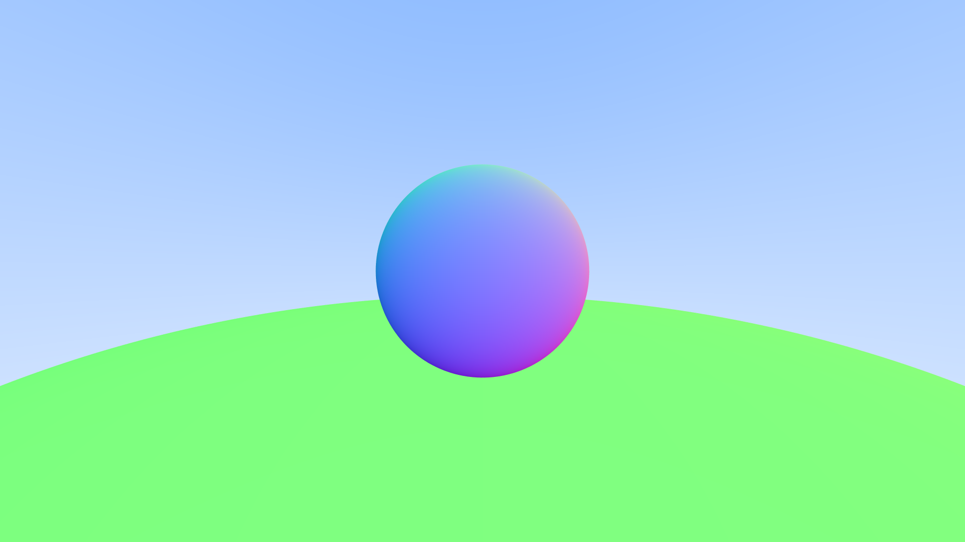
I started my render engine off by initially following along a series called "Raytracing in one weekend." I ran through the initial few chapters of that series. This started with creating very basic images, and exporting through a format called .PPM. After that was adding a basic sphere into the scene, not as geometry, but as the mathematical representation. Once that was working, I added basic anti-aliasing and a way to represent what would be the normals of the sphere, leading to the image you see here.
Once that was complete, the next step was to get some form of basic shading. I used a very basic shading model to start off with, and the first material type I went with was "Lambertian", a lambert shader, commonly refered to as "Matte shading". This refers to a perfectly diffuse material.
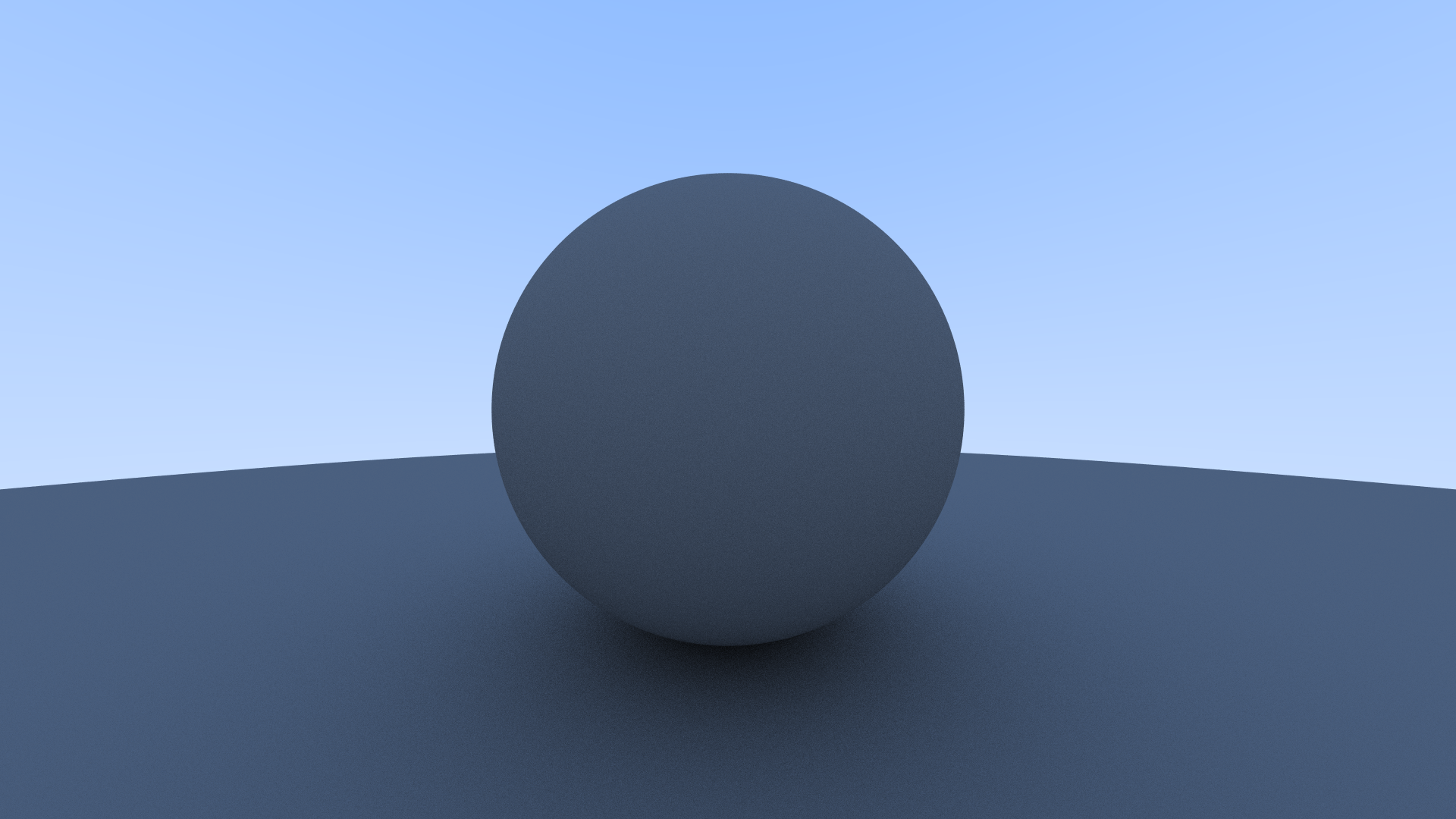
This wasn't without issue however. During this I had a error in my code when it came to the calculation of
how ambient light should interact with the sphere's that I had. This resulted in the spheres coming out as
a flat grey color with no observable depth to them.
This was caused by the direction of the light bouncing off the material going the wrong way.

The next material type on the list was metals. The shading model I was using took in 2 parameters for metals. First was the color of the metal in RGB, and the second was a 0 to 1 range value called "Fuzz", essentially how blurred the metal's reflection was.
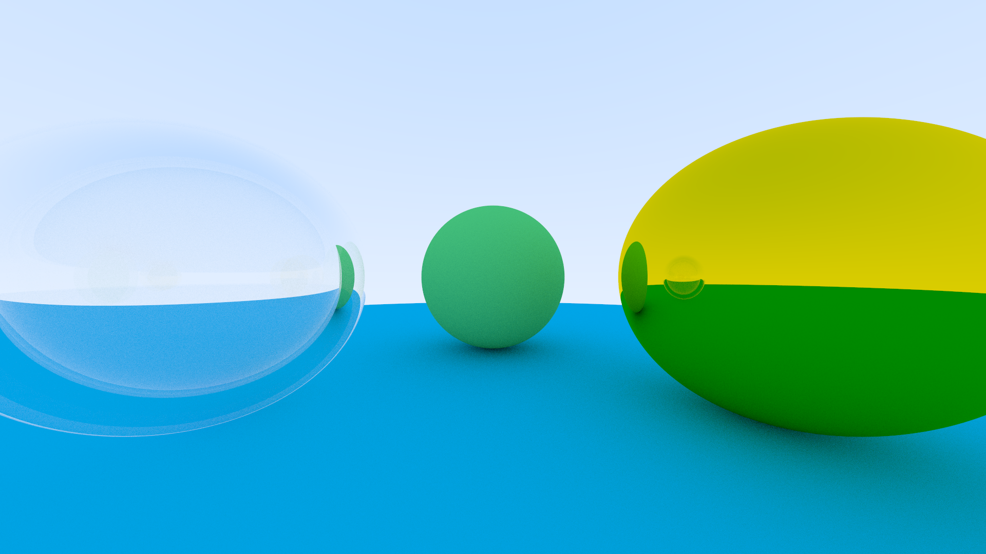
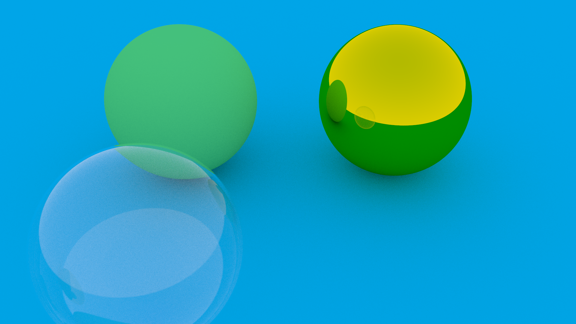
After that was programming in a transparent material. The type of transparency I am using is a pure Dielectric model. More specifically I am only using Index of Refraction (IOR) to affect the level of transparency that the material has. I decided to add a second sphere within the first glass sphere, so that the material can act as though it has thickness, rather than just being a solid block of glass.
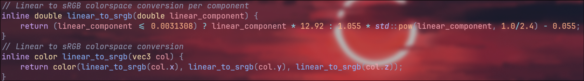
During this stage I also decided to write a system to convert my image from linear colorspace to sRGB, the images just
looked really off without having that implemented. Turns out for linear to sRGB it's a single mathematical formula. If
you're interested it's here.
linear component here refers to red green or blue, depending on which is given, and this just checks if that component is less than
or equal to 0.0031308, and if it is, then multiply by 12.92, otherwise you take the component, apply an exponent of 1 divided by 2.4,
and multiply that by 1.055, before finally subtracting 0.055 from that result.
Once I had those materials sorted, it was time to make the camera movable. The main challenge with this was that in order to render objects, you first have to convert the world from world space to camera space (space where the camera is at the center of the world), and from there you then convert to 2D pixel space, so applying a transformation to the camera meant adding the world to camera space transformation as well.
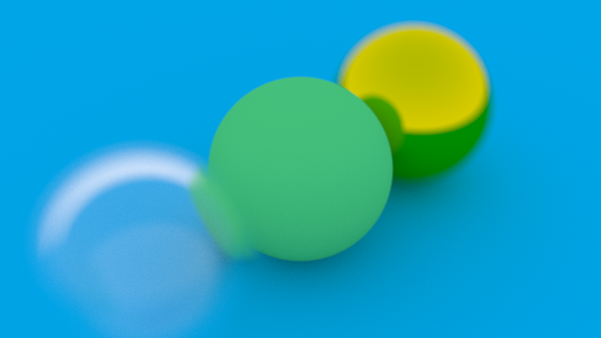
After making the camera movable, the next thing was to get depth of field working. Hopefully making the scene feel a bit less CG,
as much as you can at this stage anyway. The method used for this was to take the sample position for each pixel, and depending
on the field of view and distance from the focal plane, adds an offset in each direction to sample the color of the pixel from,
thus blurring the image to give depth of field.
Later down the line I want to convert this from a FOV model to a full camera lens model, but this does the work for now.
With all that said, I had now finished "Raytracing in One Weekend" volume one. I had perfect sphere's rendering in all sorts of
basic materials, but there was something (actually a lot of "somethings") missing from the render engine.
I had a quick glance through the other books of the same series, but ultimately none of them described how to take the next step
that I wanted to take, and so it was finally time to drop the guidebook and see what happens. Now the real question, what was the
next step?
GEOMETRY! Specifically I wanted to get .Obj files loading into my scene, USD and the rest can come later but for now I just
wanted models in my scene. Now this involved a few different steps before getting it working.
Step one, I needed a way to actually read the .Obj files into my render engine. Step two, converting those models into something
that my render engine can use. Finally step three, using those models to create something in my image, and in this case I went
back to square one right at the start of "Raytracing in One Weekend", but from the angle of implementing Obj instead of spheres,
start in a small capacity and then scale up to production seemed like the best way to handle this challenge.

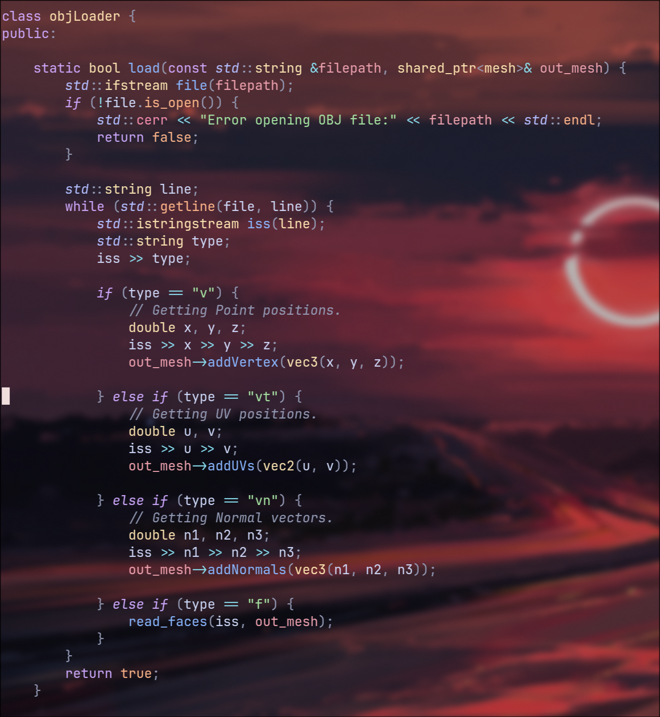
For loading the .Obj file, luckily they are just a text file with a specific formatting for vertices, normals, uvs and
faces. Through C++ I open the file line by line, and check if the first string of characters (before a whitespace) was either "v"
(vertex, the position of the point), "vt" (vertex texture, more commonly it's your UV attribute), "vn" (vertex normal) or "f"
(the face the specified vertices make up). As I checked through them I stored them in a custom class I setup, which just added
them to specific lists (in C++ this is adding to a "vector", which is a dynamically sized list in C++, but for all intensive
purposes I'm going to refer to them as lists, as that will be less confusing for anyone familar with 3D who start reading about
a vector with over 100 components).
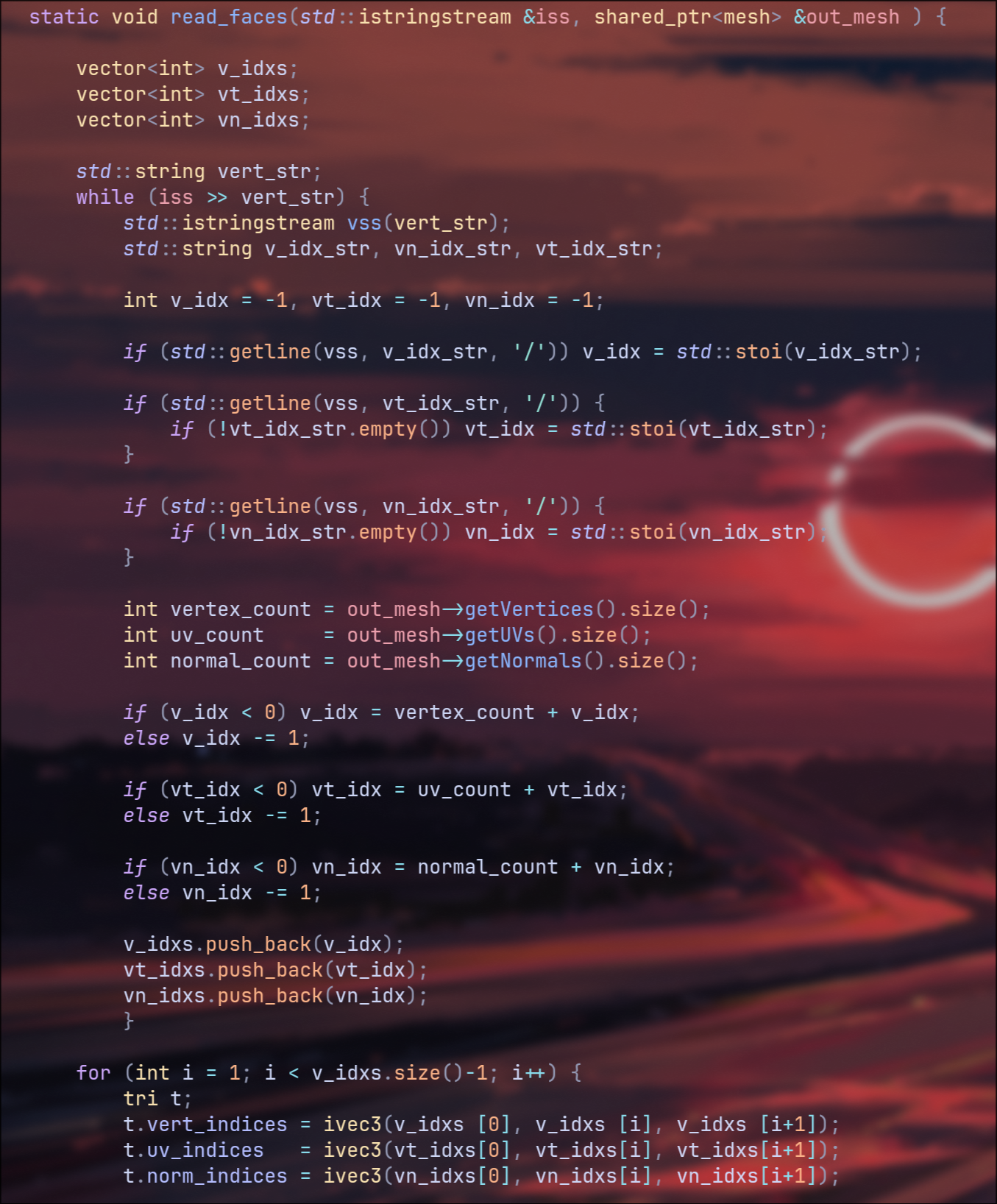
I will get to how creating faces for the render engine to use works later down the line when I start talking about implementing
quads into the render engine, but for now, the idea was to only give my render engine triangles to work with, and then I just took
the first 3 points and made a triangle out of them using the lists I gathered above.
Now for the last part of this, which was just figuring out if the triangles I had intersect with the ray of light currently being
fired from the camera. At this point I want to quickly cover something, the way light works in a raytracer is a bit strange. Rather
than a light firing rays in all directions, praying that one of those rays hits something, we instead shoot rays from the camera,
and have them bounce around in the scene until either a set number of bounces is reached, or if a light source is hit. There aren't
any light sources aside from just an ambient light in the scene at the moment and so it's just until the bounce limit is reached.
The reason for this is because firing rays from a light is incredibly expensive computationally, and so for optimisation purposes
we go from the camera, the eye of the scene, to the objects, to the lights, opposite of reality. Some render engines do a combination
of both, which is known as bi-directional pathtracing, and it's something for much much further down the line.
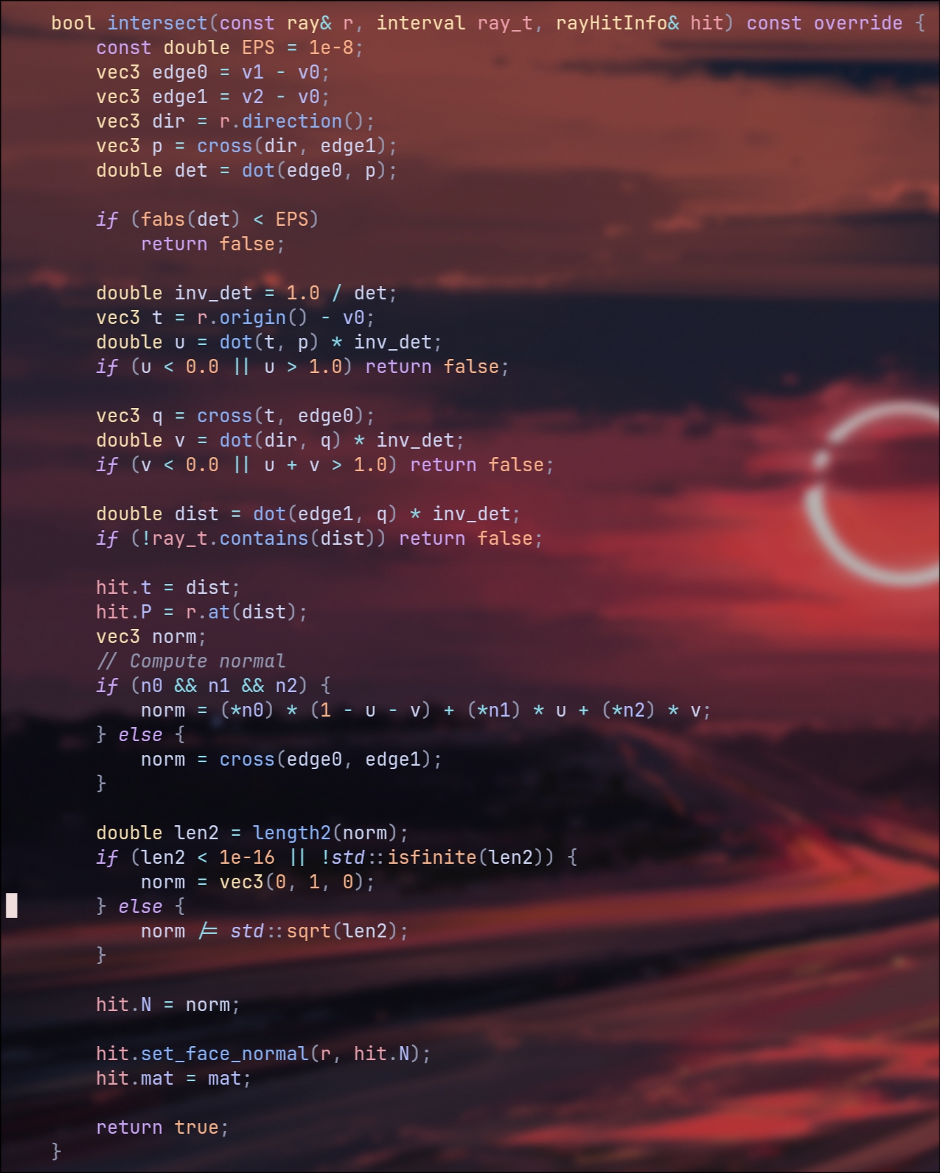
With that out the way, back to ray intersections of triangles. Luckily for me this has been studied a LOT and so we have a fun little equation
for calculating just this, "Barycentric Coordinates". The idea here is we take the 3 points, and then weight their average influence
on our triangle, all of which adds up to a total of 1. From here we can calculate that any position within the triangle will have a
positive value, and anything outside will have a negative value, and we don't have to worry about any kind of twisting since a triangle
always sits on it's given plane, meaning no matter how much you try, you can't twist it over itself, unlike something like a quad.
Finally we then check if the ray position ever passes through a positive coordinate, and if it does, we have a hit.
Now that was working, I wanted to give my mesh some color, same as before I started with normals rather than a more complex material. The reason for this is so I didn't have to worry about calculating how light bounced around my scene and off my geometry, I could just see if it did hit, and if it did then set the pixel color to the value of the normals.

Now that I knew that was working, I decided it was finally time to start looking at adding an actual material to my mesh. Lucky for me it turned out that there really wasn't much difference at all with the math for the material on a sphere, and material on a triangle, it was just a matter of setting up my triangle class so that it could be assigned a material.

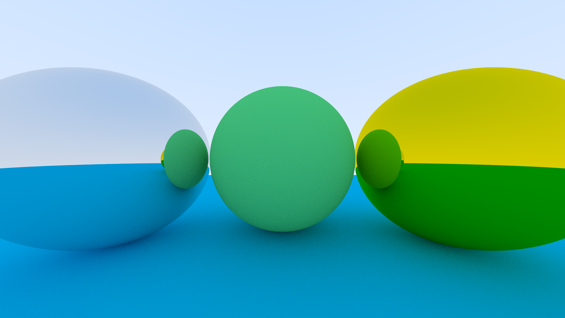
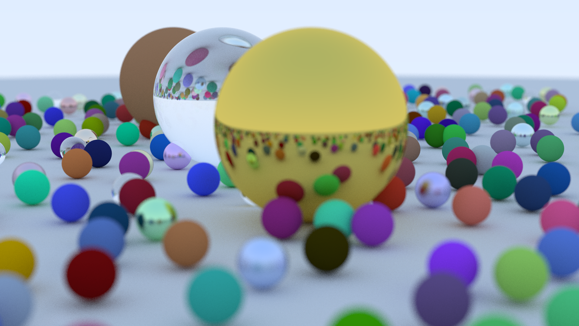
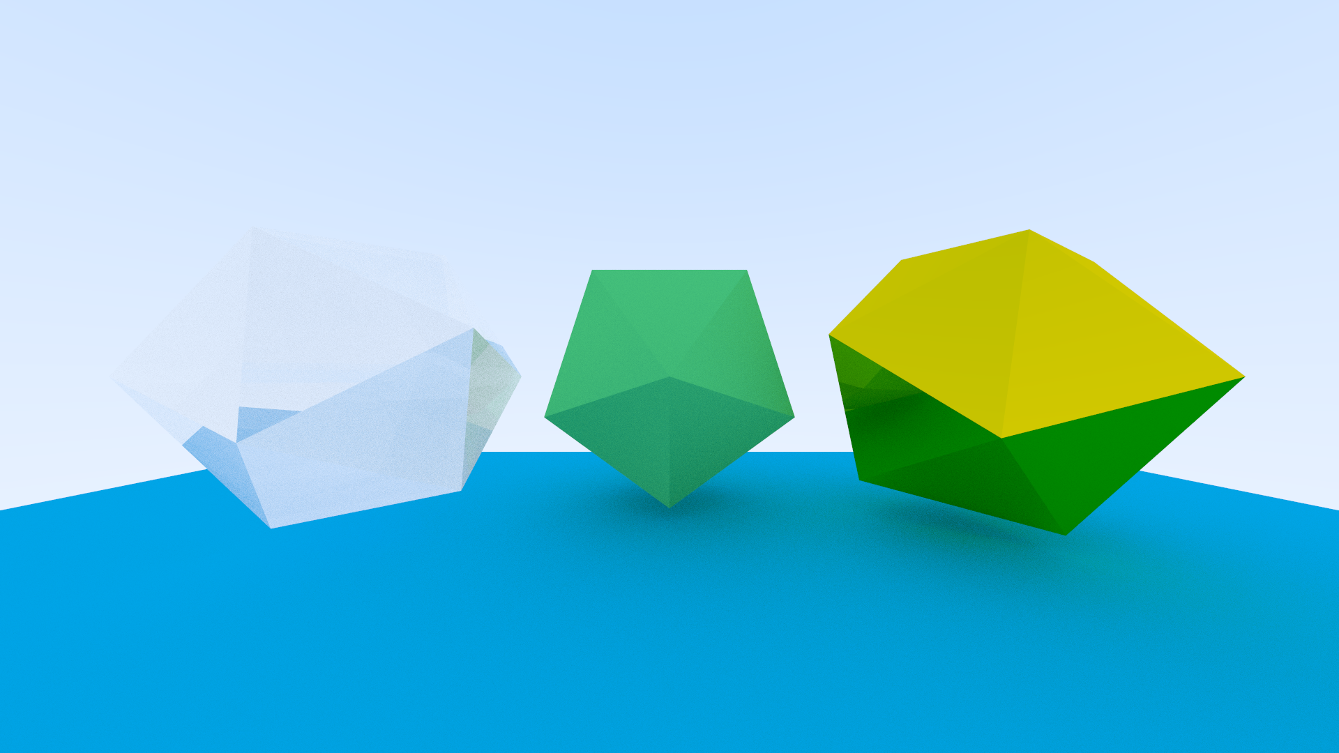
Next up was going through and recreating my scene with multiple objects. More specifically I found having a matte groundplane, along
with a matte, glass and metallic object proved to be quite a nice testing ground for my render engine, at least at this scale anyway.
Now sadly while it may sound like this had been smooth sailing so far, it really wasn't. This render is actually a good example of
one of the issues I had, and it stems from the fact that just because my code doesn't error, doesn't mean the math behind it is working
as it should be. It may be a bit hard to see, but towards all the poles on the geometry (the part of the faces nearest the points), you
should be able to see a wierd bit of banding happening, where there's this curved shadow. It's easiest to see at the bottom pole of the
center model.
This was caused from something really silly, I wasn't normalising my ray when I fired it from the camera, which I believe meant that
lights shooting from the edge of the scene were bouncing around in too large an increment compared to the center pixels, and so they
caused uneven bounces, ultimately leading to that artifacting there.
Alright and here was the fixed version, actually if you look between the render here and the one above, you can start playing spot the difference with how many things were actually being affected just because of how long the length of a light ray was.
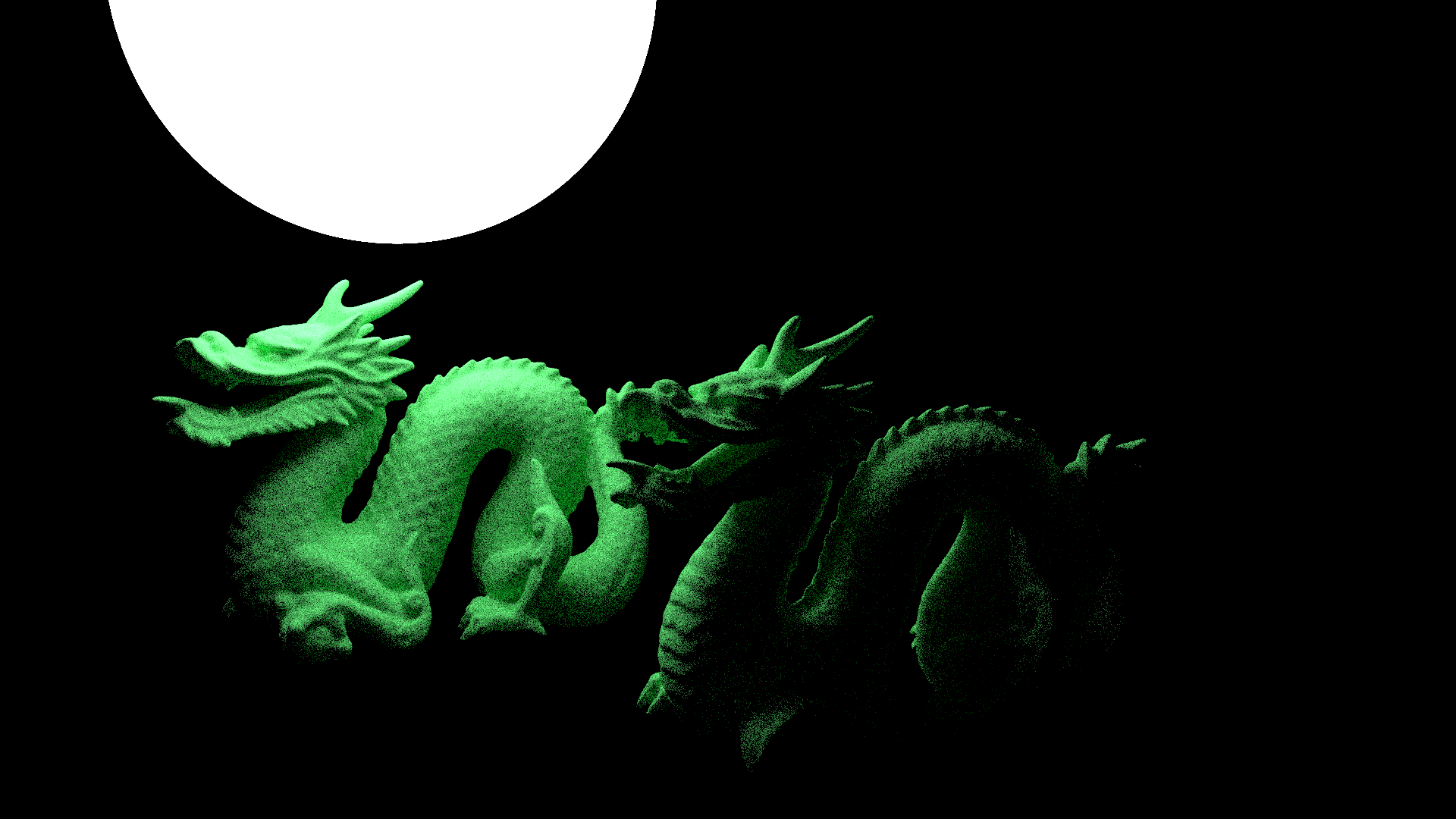
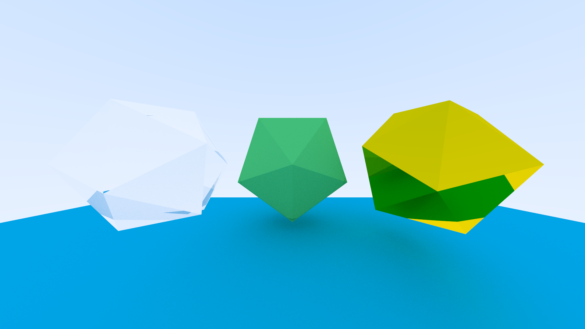
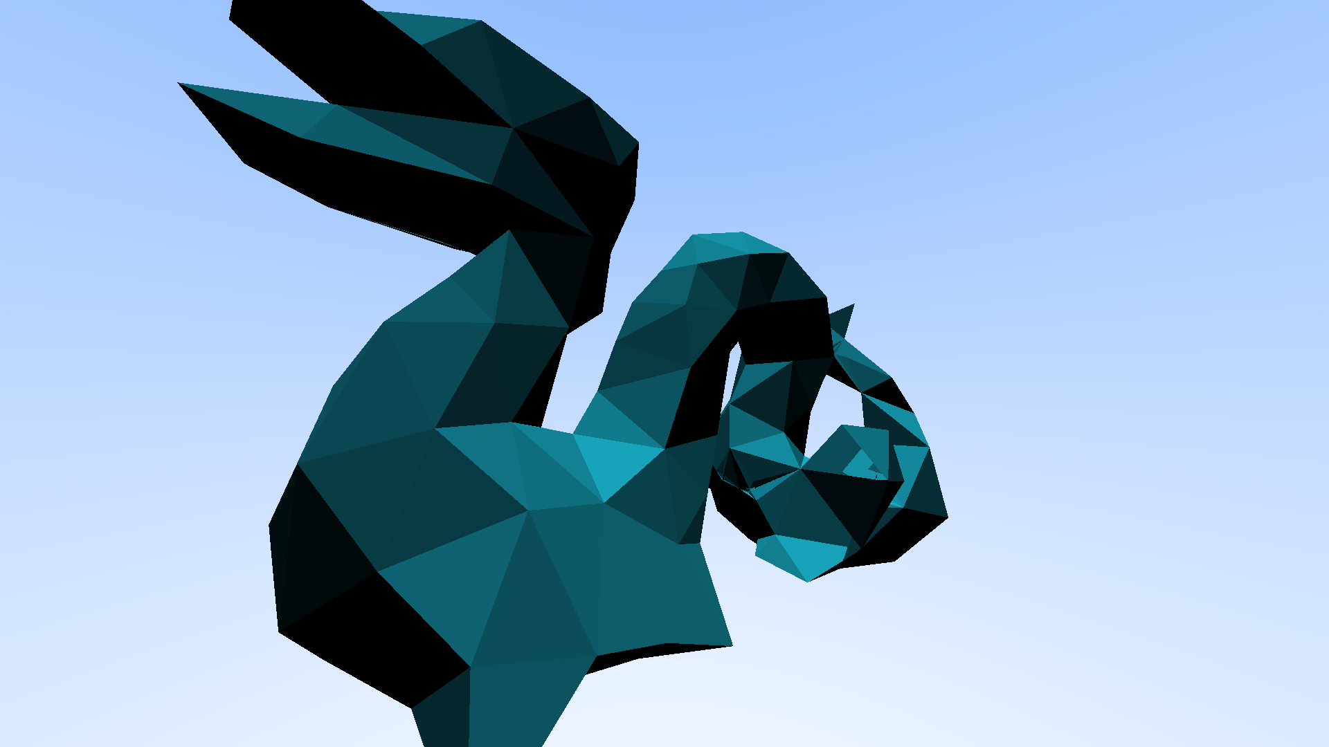
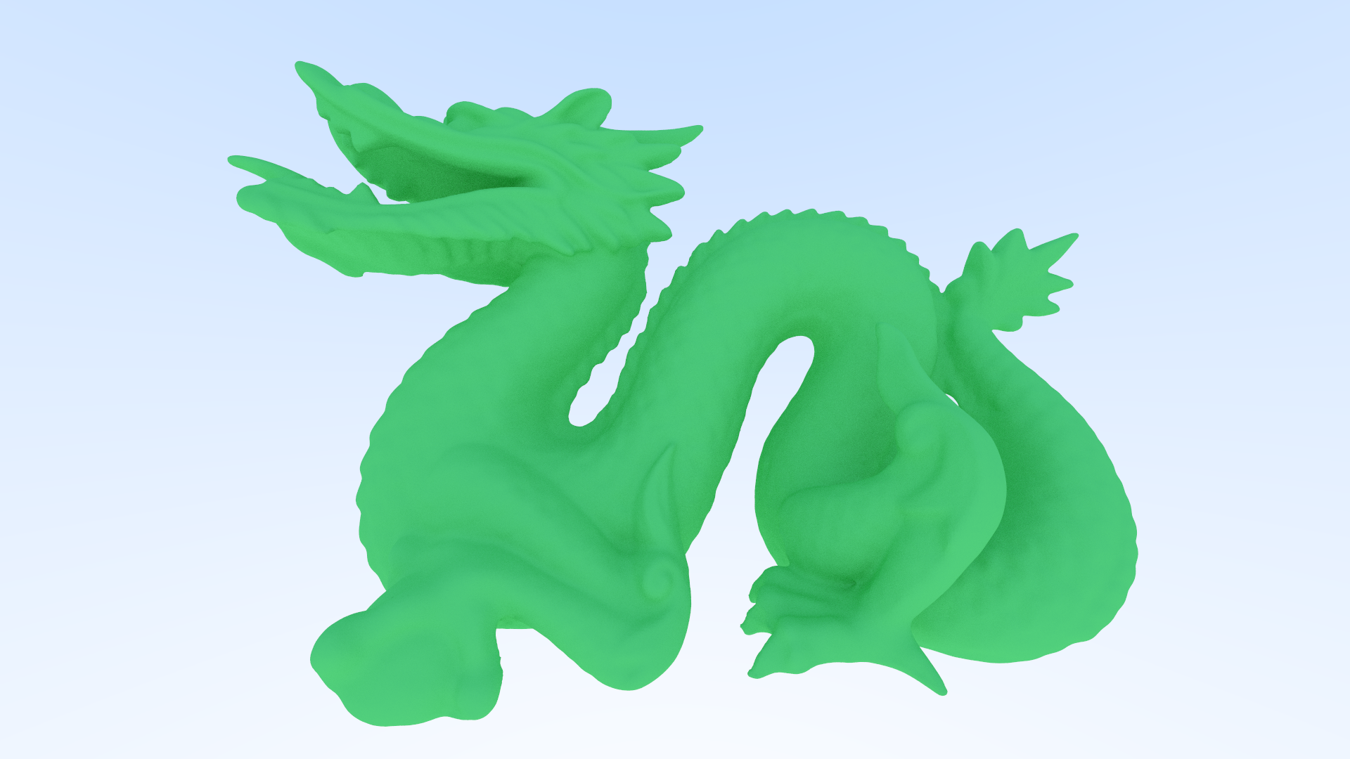
Alright I'm going to blaze through this next bit as you've seen it already, this time thought I was aiming to get a larger mesh
working. My scene at this point was maybe 100 triangles if I am being generous. I wanted to render a chinese dragon model that
often gets used for benchmarking and R&D tests, and that full mesh is ~800K polygons, so slightly more than I currently had on
hand, but don't worry, light work, my render engine had it no sweat! Annnnnnnnd it wouldn't even render a pixel after 20 minutes, nice.
Alright baby steps, I lowered my expectations for a minute and decided to go with a roughly ~800 poly mesh, much lighter but
even this was a struggle, and so my next step was optimisation to try and reach my goal of 1 million polygons.

The first optimisation technique I used was called multi-threading. I was only using one core on my laptop up until this point in
time, but it would be so much faster to use all of them, in my case I was going from 1 core to 24, so 24 times the number of pixels
rendering at one time.
Now this doesn't mean that you get 24x the performance, as nice as that would be, it's roughly 6x faster but could go up to 10x depending
on what I was doing when rendering. Still not nearly enough for that dragon mesh, it was great that I could do 24 pixels at once but if I
couldn't even get one pixel to render what was the use putting 24 pixels on at a time if none would render anyway?

Now as for multi-threading specifically. I set up a threadpool (a class that automatically manages all the threads on my laptop) and from there I had different functions that I would call at different times in the rendering process. What that means is that when a job started, my threadpool got all the workers, and then one by one asigned them a task from that job, and would remove them from the currently available pool. Then when a worker finished their task, they would feed back the result, clean up any residual data, before finally being added back to the active pool and the cycle would start all over again until the job was complete.
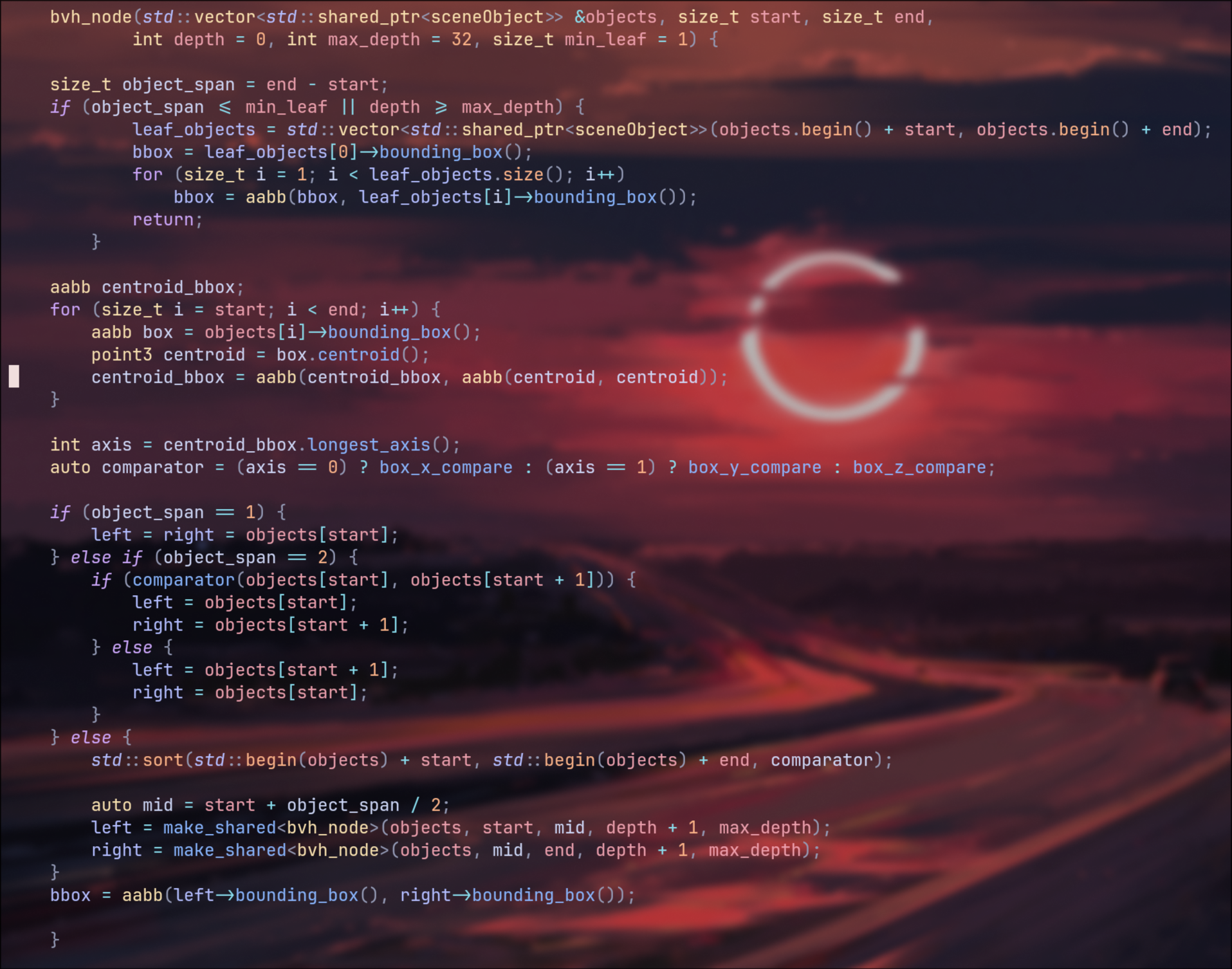
Now that did yeild some nice results, we did finally have a mesh of roughly 8K polygons working, but I definitely needed some bigger guns if I was going to get the full resolution model working. It was time for some more optimisation! This meant I needed to finally start looking at a very powerful algorithm for speeding up calculations like these, A Bounding Volume Hierarchy, or BVH for short.
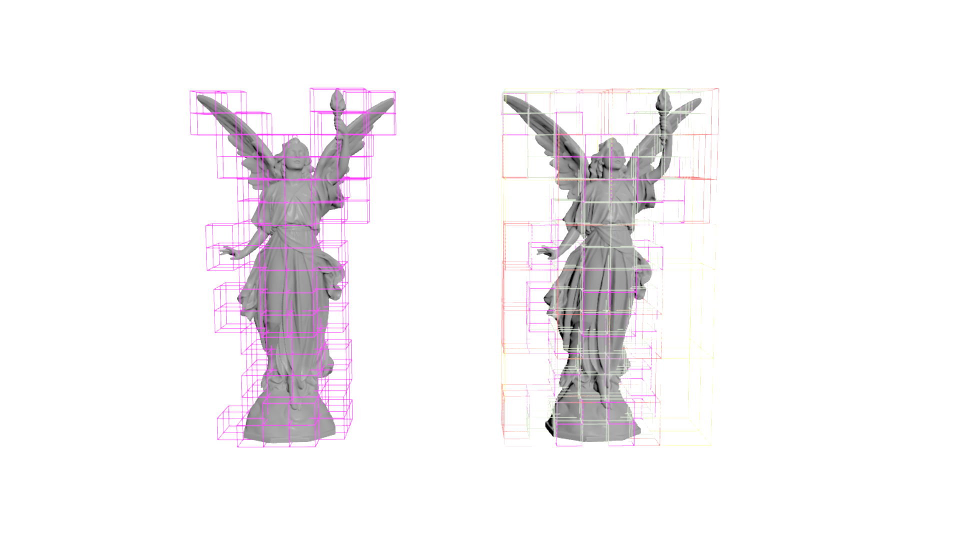
The idea behind a BVH is to take a given mesh, create a bounding box from it, and then recursively divide that bounding box until you get
a much more reasonable number of boxes to loop through when a ray is fired.
Up until this point I had been doing something roughly along the lines of this: Lets say we have 1 million polygons, since that's what I was aiming
for here. Every time a ray was fired from the camera, the render engine had to go through every one of those million polygons, and check if the
ray intersected with that polygon. Then lets say we have 20 samples per pixel, meaning it had to do that 20 times! 20 million processes for a
single pixel. A 1920x1080 image is roughly 2 million pixels, so 2 million times 20 million and this was getting into beyond silly teritory.
Instead, with a BVH, we check the bounding box, if the ray missed it, we continue, thats already 1 process instead of 1 million, if it hit however,
we would then split the bounding box in half, check each half, and we repeat this until we get to a recursion depth limit, I set this limit because
otherwise the BVH would try to create bounding boxes until it got down to a single polygon per box, at which point it was another several million
calculations to make the BVH in the first place. Once it reached that recursion limit, it then looped through all the polygons in that bounding region,
and then calculated any light bounces occuring. You would be looking at ~50-100 checks per sample now, which was a much nicer number to work with, putting
it bluntly.
The image to the right here is a Visualisation of BVH construction in Houdini, to the left, is the bounding boxes at roughly depth 10. On the
right, you have all the depths up till that same depth of 10, but overlayed on top of one another, you can see as the depth increases, any bounding boxes
that don't have any primitives inside them get culled.
With that out the way, it was now time for the big test, could it handle the full resolution dragon. Turns out, yes, yes it could. It took me
a little while to realise about the depth recursion limit that I spoke about earlier, so at first it didn't want to play ball, but once I added
that, it was happy to start rendering.
There was one other little issue though that cropped up during this time, NaNs! Not the kind that make amazing roast dinners sadly, the kind that
break your renders. NaNs stands for "not a number" and this issue caused my .PPM file format to break. PPM basically just lists numbers between
0 and 255 representing red, green and blue respectively, the issue that happens with NaNs in this case, instead of 0 to 255, a NaN value defaults
to the lowest 32 bit integer number, -2,147,483,648 to be specific, and that in turn makes any pixels after the NaN in my image break and just
don't show up. The fix was just adding a failsafe where if the length of the ray vector was too short or not a finite number then set the vector
to point directly from the normal.
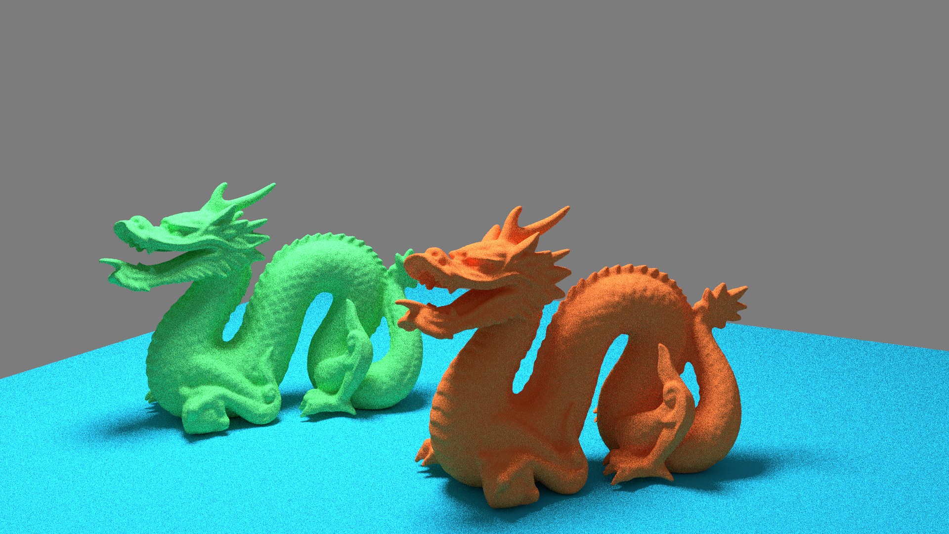
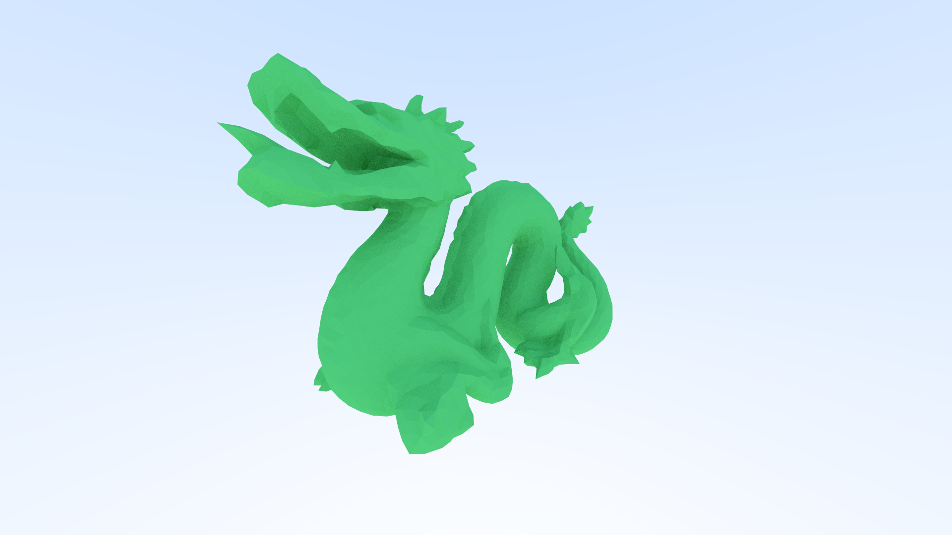
After that I started having a play trying to get different renders working, I now had 2 dragons, so we had hit the 1 million mark, and I was very happy
at this point. My first test was running with just lambert shaders.
The other thing that I did at this point was finally implementing quads.
Quads gave me a lot more options for what I could add to my render engine, and I no longer needed to triangulate all the meshes coming into the render engine beforehand. Now the easiest way I thought of to deal with rendering quads, was rather than triangulating outside of the render engine, why not do it internally during the file reading stage. The idea behind this, I applied procedurally rather than hard coding, which was just looping through each face, and taking vertex 0, the vertex of the current loops number, and then that number +1. So for example, you would have the points 0, 1 and 2 making a triangle, and 0, 2 and 3 making another. This also meant if I was to load in ngons, it would accept them, but if you had very unstable geometry then there would definitely be artifacting, a future problem but its not a high priority at this moment in time.
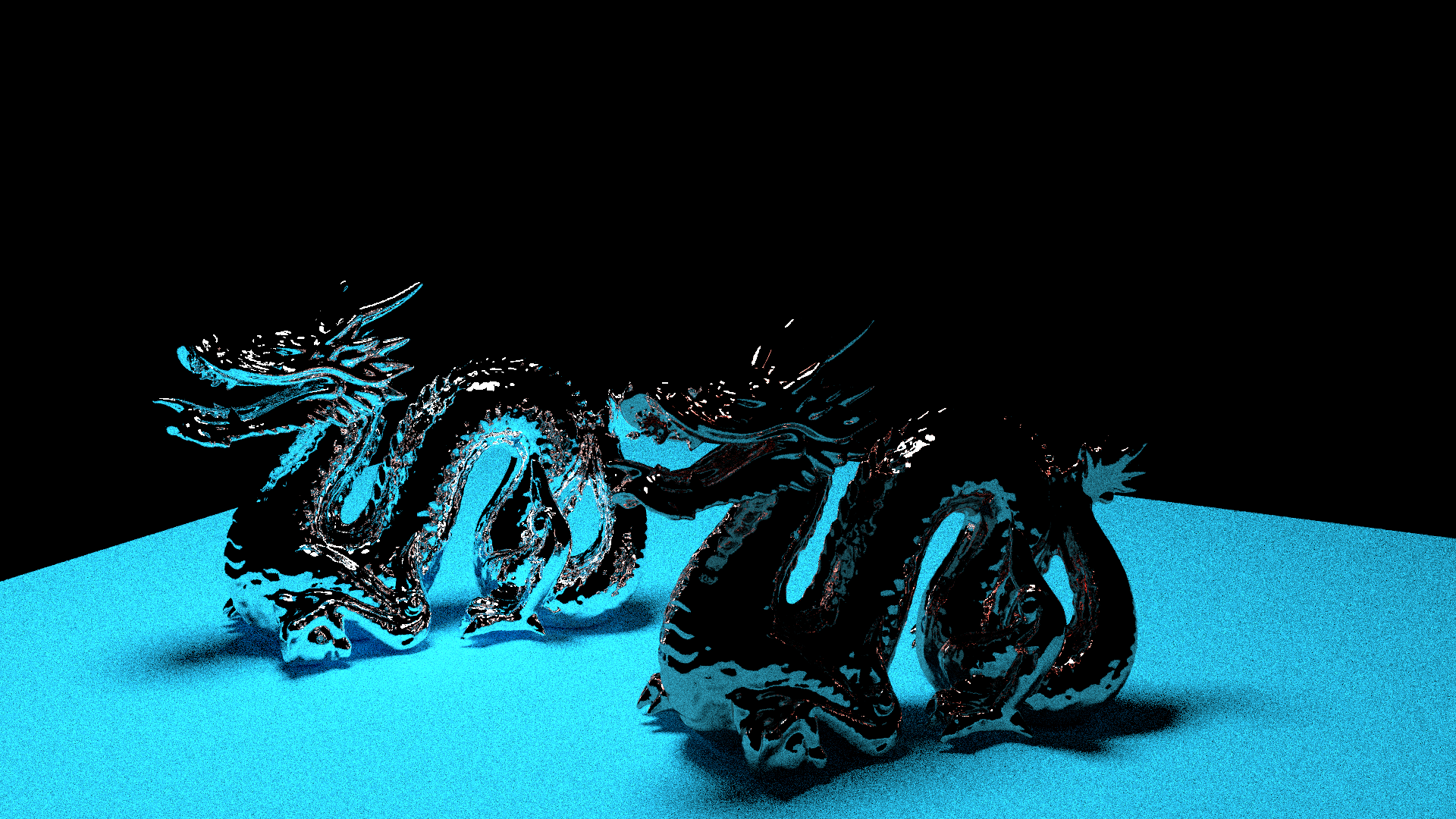
After that I tried rendering the dragon pair with field of view. I chucked on 2 metallic shaders with fuzz enabled and this was the result.
Next up, I implemented an emissive texture. The reason for this was actually to use it as a light source, in the long run I plan on playing
around with different ideas for lights, but this works at the moment. The main thing that will affect this is implementing more advanced
shaders, in particular when I add physically based materials, but that will only be happening after upgrading to a path tracer.
I decided to reuse the mathematical spheres for this light actually, was nice to finally have another use case for them now since they had
been relegated to the quiet corner ever since I started reading in geometry.
After that, I wanted to see how the light would interact with a metallic shader, and so I chucked on some chrome and set it to render. Here was the result of that experiment.
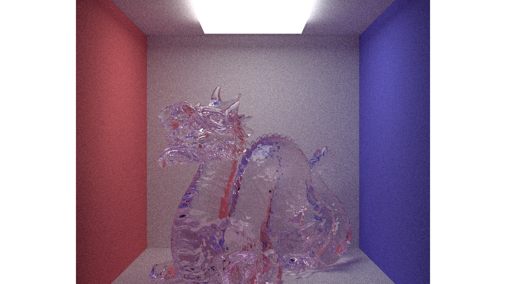
Next, I wanted to use a cornell box, I felt that using something like this would make it a lot easier to compare to other engines and such. This is also a very common model used for benchmarking, along side the dragon I was already using, and so I fired off my first render of it here.
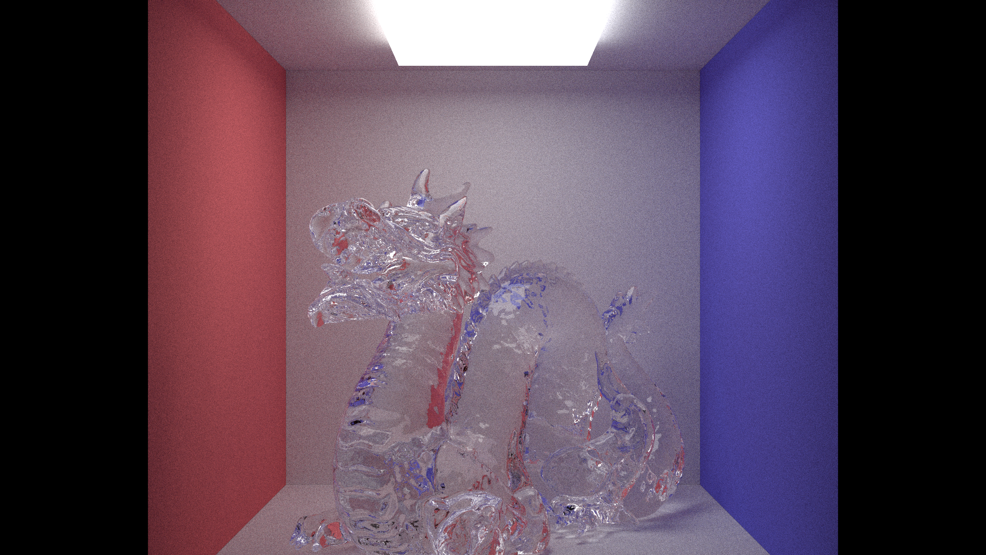
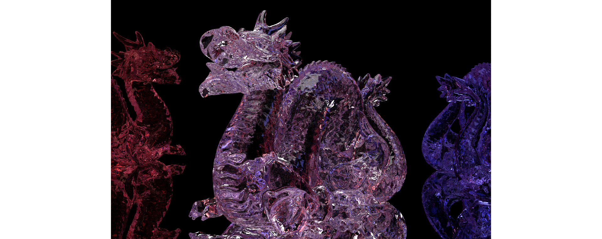
I then had a fun idea, how about adding an absorption property to the glass. What this means is if the absorption of the glass is set to 0, 1, 0, it will completly absorb the green channel of R,G,B, and then bounces back purple. That's exactly what you see here. This is the same kind of thing that water does the deeper you go, starting with the red channel.
After all of this, now I finally decided that my render engine was at the stage where I would should implement .exr files. And so also
came my first use of an external library, the library responsible for exr files. Up until this point, everything I had in my code was
written from the ground up, be it the definition of a vec3 (a vector with 3 axis) all the way to my materials and rendering.
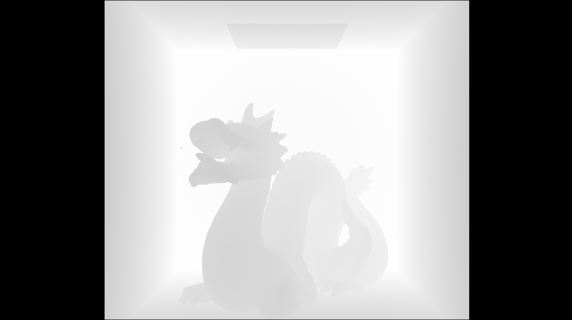
The advantage of this now is I was able to add data passes, this one here is a depth. When a ray collides with a mesh it stores the
length of that ray, this has a few advantages when it comes to a bit of optimisation, but in this case is acts as my depth pass value.
Next up was normals, which luckily are stored in .obj files, but if for some reason they hadn't been stored, then I calculated the face normal and used that which was slightly less accurate, but it worked for now.
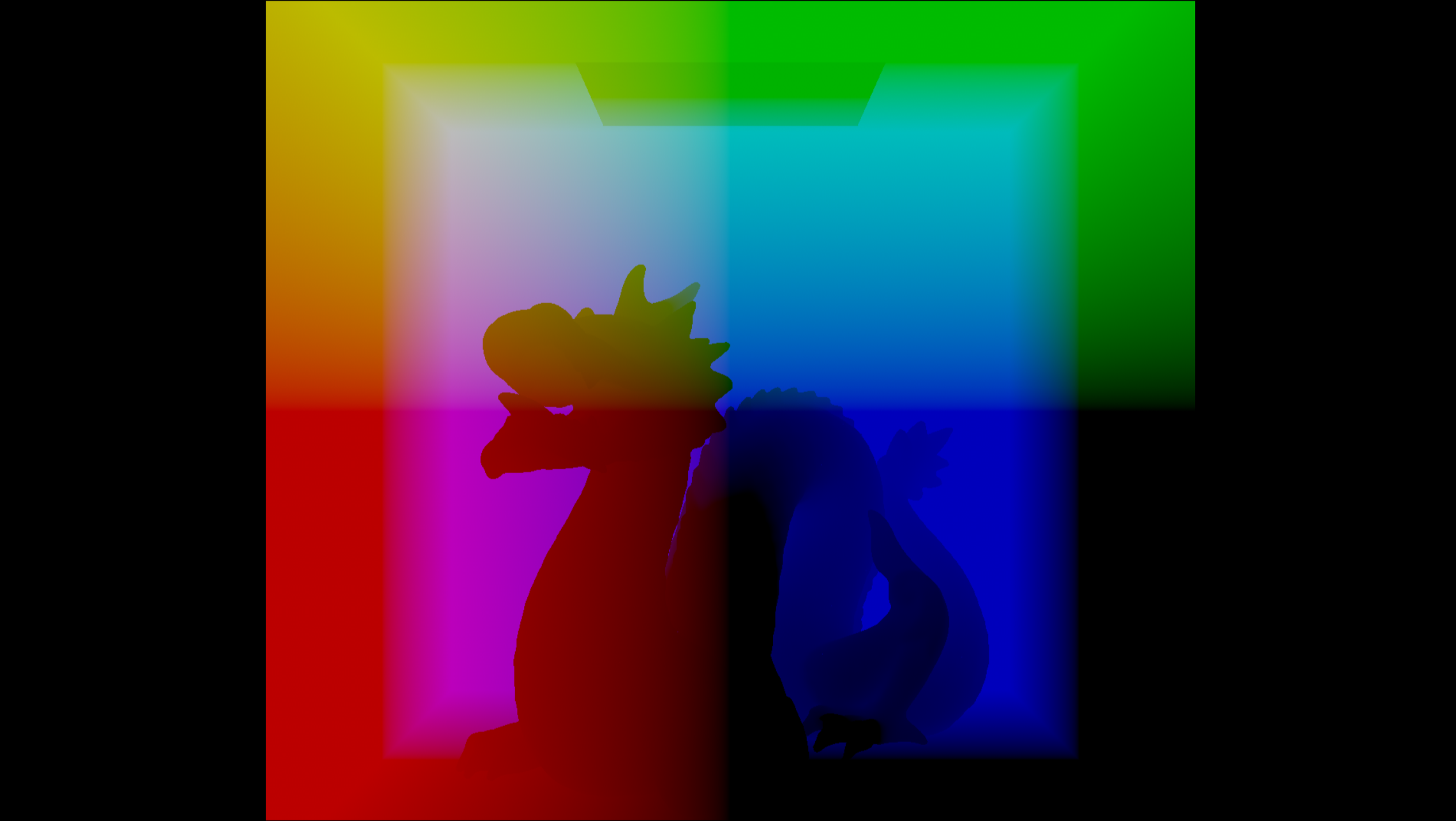
Next was world space position, which again was just sampled from the ray when it hits the mesh.
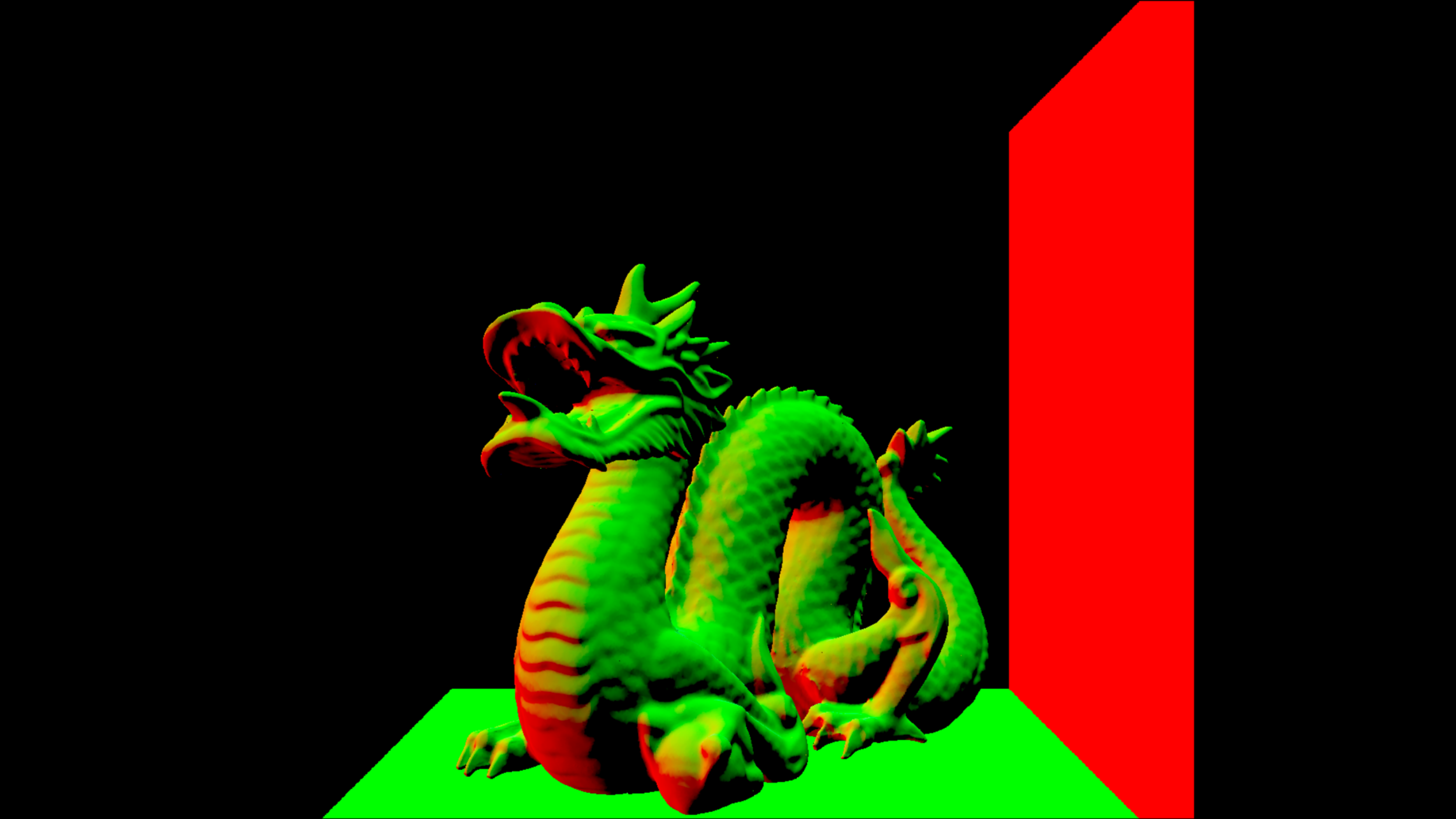
Now for one of my favourite data passes: Camera facing ratio. I don't really have a proper reason for it being one of my favourites,
I just really like the way it looks and it's got a satisfying math element to it. The way this works is by calculating the direction of
the normal, which in turn is the direction the face is well, facing. Then we use a dot product to calculate if the ray and the normal
are facing towards each other, and based on that we set the value for the facing ratio, a dot product of -1 means the ray and normals
directly face each other, and I set a value of 1 in the red channel. If the dot product gives 0, I return 0.5 in the red channel,
and anything further than that is on the other side of the mesh and so you can't see it. The reason I return 0.5 instead of 0, is because
0 is the blank space where no geometry is.
Ok I said I didn't have a proper reason for facing ratio being one of my favourites, but it was the inspiration for another small project
I worked on a while back. Back when Houdini's Karma didn't have facing ratio, and I didn't know how to properly set up a custom facing
ratio pass. I stumbled upon Entagma's youtube video on "Building a DIY Render Engine Like It's 1975". Now this version I believe was to
take those passes and send them to AI. I decided to modify it a bit, add procedural camera scaling (the video version is locked to a square
screen ratio), and then create an exr from a bunch of 2D Houdini volumes with values of attributes, a data pass generator if you will. It
was my first time dabling in render engine R&D. Just a bit of fun trivia for you.
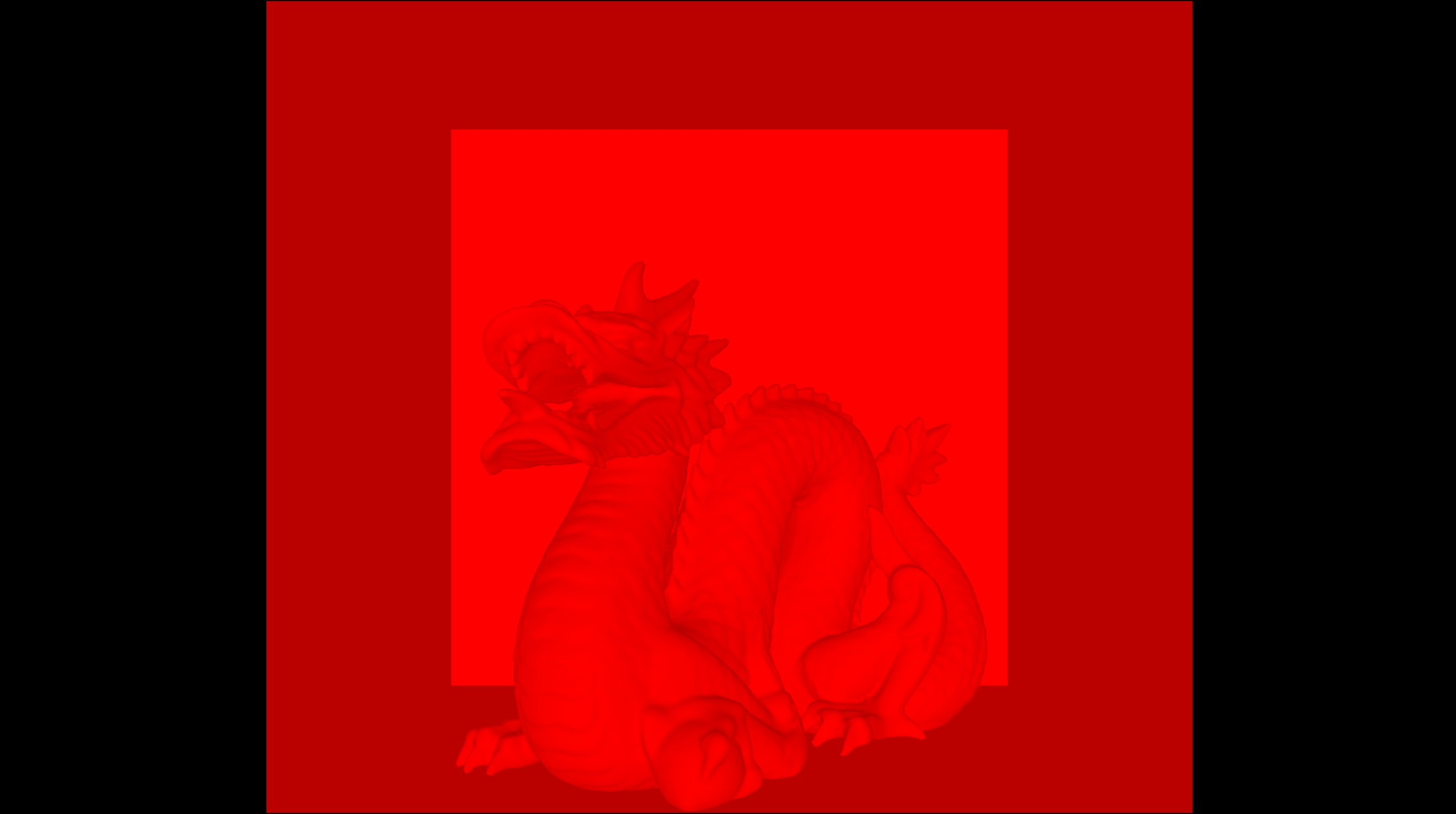
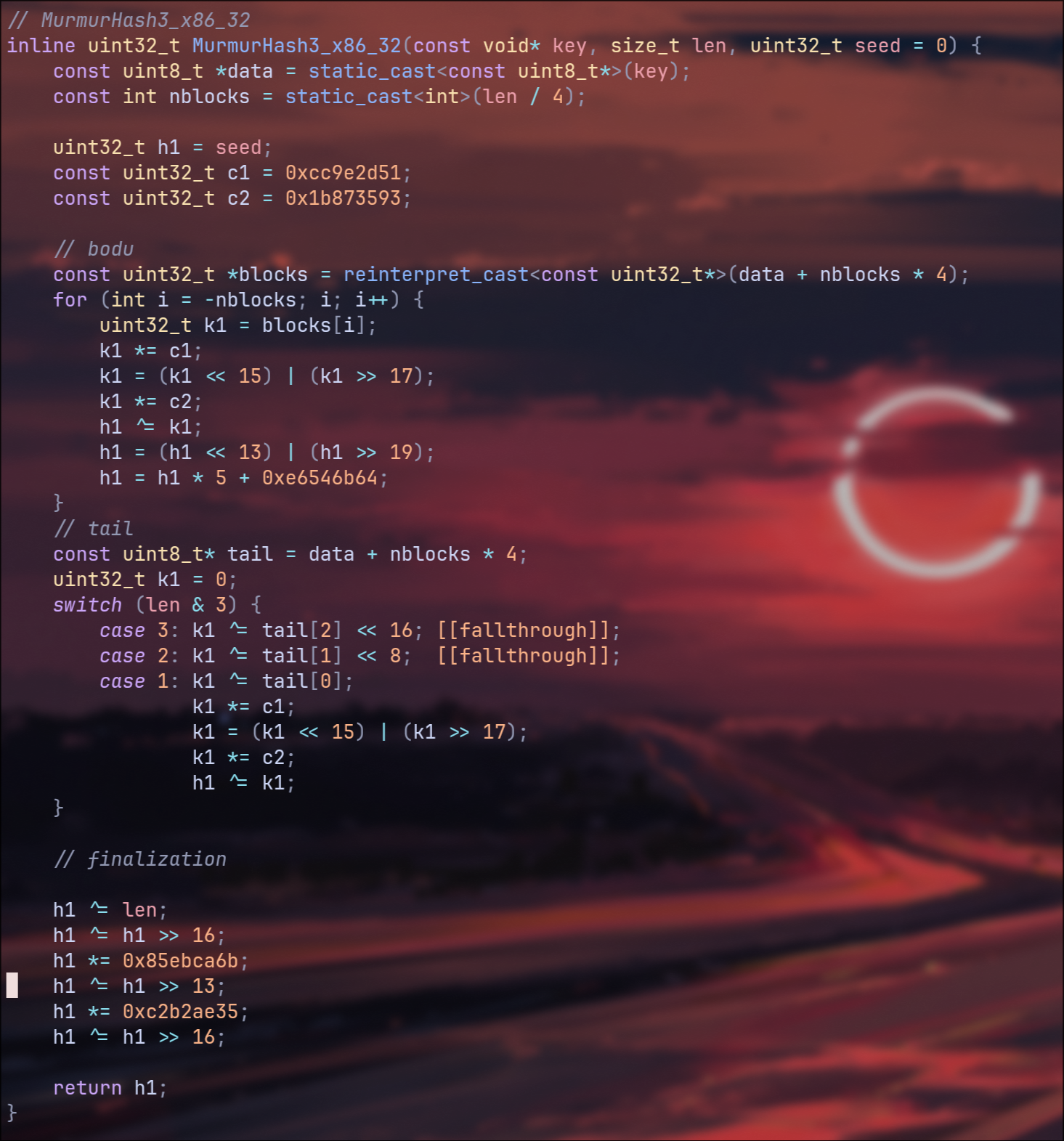
Finally we got onto cryptomatte. The issue with this was that it required very specific metadata. So not only did I now need IDs for my materials and meshes within my scene which then got set to the cryptoid, but I also needed encryption among other things.
Speaking of encryption, I needed to figure out what kind. Luckily I could use Nuke to read the metadata from any exr files rendered out of Houdini with cryptomatte enabled.What this gave me was that the encryption method used for nuke was something called murmur_hash3, and luckily enough again, wikipedia happened to have a C based language implementation of this encryption. I then just needed to setup writing it out alongside the rest of my data passes, which in turn did make me need to overhaul the entire way I was writing out exr files, but in the end it worked and now I had working cryptomattes.
And with all of that, you've reached where I am currently at with my render engine.
Thank you for reading and if you have any suggestions for improvements, or any questions about my work, please reach out to be via
the email below!
Now if you're interested, the next plans for this project are roughly as follows:
Work out how to do scene serialisation: I am creating nodes in Houdini that will write out to a .json file that my renderer will read in
and convert into a scene. In this way I can do lookdev inside of Houdini, and there's potential here to explore GLSL realtime shaders.
After that is converting my raytracer to a path-tracer, and then I will start working on physically based materials.
From there I want to try playing around with some more abstract things, there's a lot of optimisations and small quality of life features that
I will implement in between this when I don't quite have time for the larger elements, but a big one I've been picturing was trying to implement
spectral rendering, using wavelengths rather than RGB values so that I can get iridescent textures among other things.
There's also a world where I span this off in the direction of interstellar, probably as a side module or a seperate project in hindsight, but
creating a render engine that can bend light around a black hole does sound very fun.